
Squeezing Bass Out of 10 Watts: Designing a 3D-Printed Folded Horn Speaker
In an open-air environment without room boundary gain, 10 Watts through a standard sealed or ported enclosure will easily get lost in ambient noise. Instead of increasing the electronic power budget—which would require more expensive amplification, complex step-up converters, and bulkier battery packs—our aim is to solve this mechanically with a folded horn design.
Can we use a complex, 3D-printed folded horn enclosure to maximize acoustic efficiency and project high sound pressure levels (SPL) from a low-power source?
The Physics of Horn Loading
In a standard direct-radiator setup, a small speaker cone is highly inefficient because it suffers from a severe acoustic impedance mismatch with the open air. The low radiation resistance means the mechanical energy of the cone is poorly coupled to the medium, resulting in low efficiency (often below 1%).
A horn operates as an acoustic transformer, matching the high acoustic impedance at the driver cone to the low acoustic impedance of the free air.
By placing an uncompressed entrance channel in front of the driver and gradually expanding the cross-sectional area to the exit (the mouth), we transform air variations along the flare path into an efficient radiating wave. This drastically increases the acoustic power output of the driver—often yielding an efficiency gain of $3 \text{ dB}$ to $6 \text{ dB}$ across the mid-bass and midrange in a compact enclosure.
To keep the speaker portable and rugged, a long, straight horn is unfeasible. We need to fold the internal acoustic path back on itself. A folded horn configuration compresses the required path length into a compact, rigid geometry where internal partitions double as structural bracing to minimize panel resonance.
The Challenge: Defying the Limitations of an Inexpensive Driver
The heart of this project isn’t about making an inexpensive speaker just to save a few Euros. It’s an exercise in optimization: exactly how far can we push a modest, off-the-shelf driver by wrapping it in an uncompromising, highly engineered enclosure?
To test this, we choose the FaitalPRO 3FE25-4F driver. At roughly €20, it’s remarkably inexpensive. But a closer look at its construction reveals a lot of hidden potential:
- The Voice Coil: A $4 \text{ Ohm}$ setup paired with a relatively strong motor structure for its size, pushing out a baseline sensitivity of 91 dB (1W/1m).
- The Material: A weather-resistant treated paper cone, making it inherently rugged enough for outdoor environments without requiring a fragile composite material.
On paper, this driver is fantastic for an outdoor build, but its electro-mechanical specs present a very narrow tuning window:
- $Q_{ts}$ (Total Driver Q): 0.66
- $V_{as}$ (Equivalent Volume of Compliance): 1.3 Liters
Because of its relatively high $Q_{ts}$ ($0.66$), placing this driver into a traditional throat-compressed horn (where the entrance slot is smaller than the cone area) would backfire. High compression requires massive motor force to overcome back-pressure; squeezing a high-$Q_{ts}$ driver through a tight throat would choke the cone, trigger severe harmonic distortion, and create massive response peaks.
Our goal is strictly maximum acoustic output (dB efficiency), not high pressure compression. By maintaining an expansive entry throat ($CR < 1$), we give the driver room to move while letting the expanding horn profile pump out pure sound pressure.
Supporting Hardware
The Bill of Materials is highly streamlined to stay within the €100 limit:
- The Amplifier: A €6.50 integrated Bluetooth module running on a 5V Type-C input, featuring an integrated battery management circuit for a 3.7V LiPo cell (pulling roughly 3.2A continuous at full 10W output). (Link)
- Signal Correction: The module features an onboard Parametric EQ (PEQ) chip. This will allow us to calibrate out internal standing-wave reflection peaks inherent to folded horn paths.
- The Structure: PETG filament. We chose PETG over standard PLA for the 3D-printed enclosure because of its superior impact resistance and UV stability—crucial properties for a speaker meant to survive baking in the sun at a backyard BBQ.
- The Drivers: Two FaitalPRO 3FE25-4F units (€20 each). (Link)
The Engineering Questions
By committing to a 10-Watt amplifier and a €20 driver, we've set a high bar for our enclosure design. We will have to solve three core technical challenges during the design phase:
- High-Frequency Beaming? Horns increase directionality. While great for projecting sound across a yard, it can narrow the listening angle so tightly that the speaker only sounds full if you are standing directly in front of it. We have to design a mouth geometry that preserves wide off-axis response.
- Path Length vs. Mouth Boundary Loading? The low-frequency cutoff of a small horn mouth is physically limited in open air. However, by positioning the mouth near a hard boundary (like a table surface or rear wall), we can artificially extend the effective flare length and mouth surface to lower our low-end extension.
- Battery Solution: Delivering maximum unclipped power on a single 3.7V LiPo cell requires careful current monitoring so the amp board's internal boost converter doesn't brown out during heavy bass hits.
Designing the Body: Calculating the Rear Chamber $Q_{tc}$
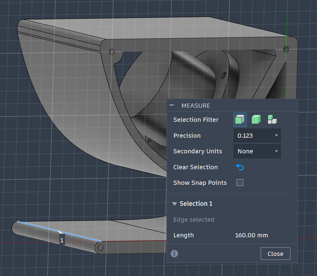
Converting acoustic math into CAD requires balancing driver specifications with real-world physical boundaries. Because our 3D printer limits us to a maximum build volume of $256 \times 256 \times 256 \text{ mm}$, we locked the overall internal depth of the enclosure to a fixed $160 \text{ mm}$. This provides a compact footprint while leaving enough clearance for wall thickness and mounting hardware.
Behind the speaker cone sits an enclosed rear compression chamber. This sealed pocket of air acts as a mechanical air spring working in parallel with the driver’s suspension compliance. To size this chamber, we start with our chosen FaitalPRO 3FE25 driver datasheet parameters:
- Total Quality Factor ($Q_{ts}$): $0.66$
- Equivalent Compliance Volume ($V_{as}$): $1.3 \text{ Liters}$
- Effective Cone Area ($S_d$): $33 \text{ cm}^2$ ($0.0033 \text{ m}^2$)
In a standard indoor monitor, engineers typically target a total system quality factor ($Q_{tc}$) of $0.707$ for a flat, critically damped low-frequency response (which would require an impractically large $8.8 \text{ Liters}$ for this driver). However, open outdoor settings cause low-frequency energy to dissipate rapidly. We deliberately target a higher $Q_{tc}$ of $0.905$, which introduces a localized energy hump right before the bass rolls off, giving the speaker necessary mid-bass punch.
Working backward through the standard closed-box alignment formula, we calculate the exact internal volume ($V_b$) needed to hit our $0.905 \text{ Q}_{tc}$ target:
$$Q_{tc} = Q_{ts} \cdot \sqrt{\frac{V_{as}}{V_b} + 1}$$
$$0.905 = 0.66 \cdot \sqrt{\frac{1.3}{V_b} + 1} \implies V_b \approx 1.474 \text{ Liters } (1,474,000 \text{ mm}^3)$$
Dividing this target volume by our fixed $160 \text{ mm}$ layout depth dictates a 2D rear chamber profile of roughly $92.1 \text{ cm}^2$ in our CAD sketch.
Horn Math: Sizing the Throat, Mouth, and Lower Cutoff ($f_c$)
With the rear chamber established, we turn to the front-loaded folded horn tunnel. A horn acts as an acoustic gear shift, matching the light air to the movement of the driver cone.
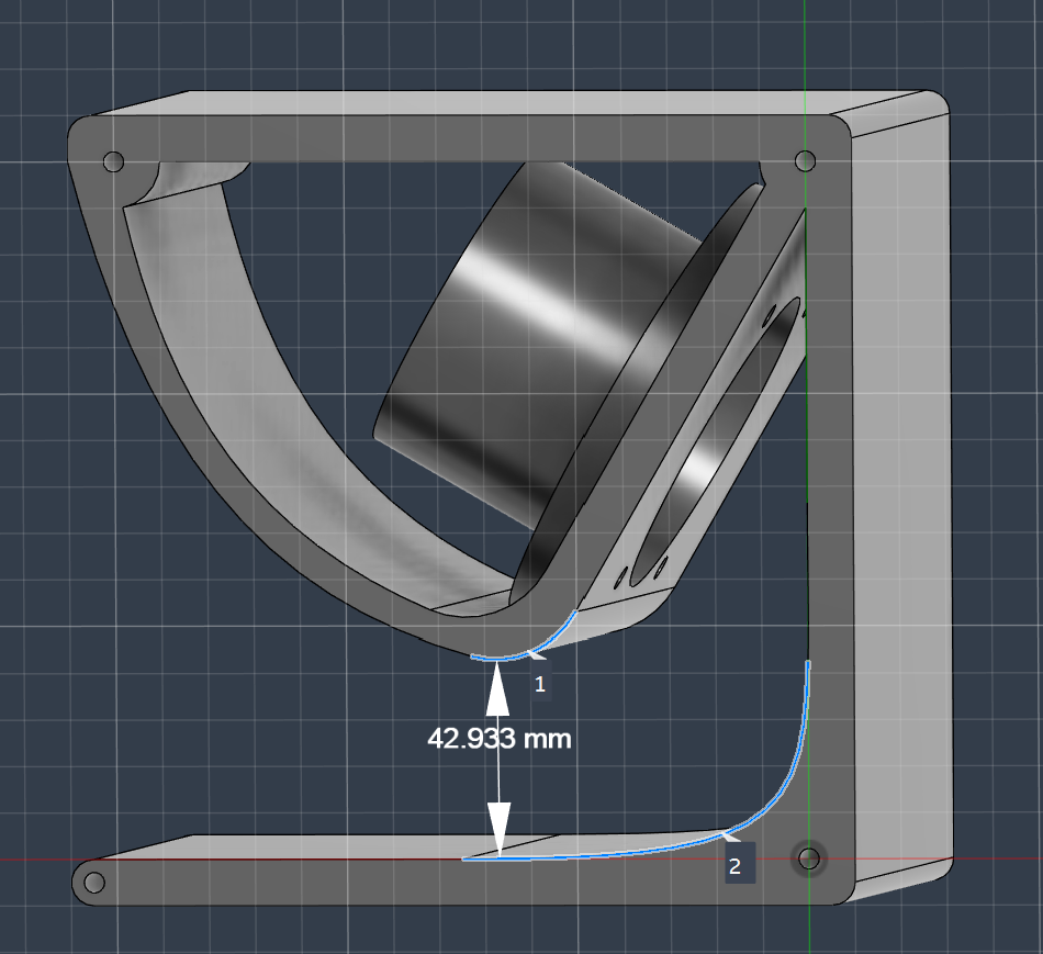
Because our driver cone fires directly toward a curved rear wall before turning into the main expansion channel—with a $30 \text{ mm}$ gap at the driver center across a $160 \text{ mm}$ cabinet depth—our acoustic entrance throat area ($S_t$) measures:
$$S_t = 160 \text{ mm} \times 30 \text{ mm} = 4,800 \text{ mm}^2 = 48 \text{ cm}^2$$
Comparing this to our driver cone area ($S_d = 33 \text{ cm}^2$):
$$CR = \frac{S_d}{S_t} = \frac{33 \text{ cm}^2}{48 \text{ cm}^2} \approx \mathbf{0.6877 : 1}$$
This confirms $CR < 1$, ensuring zero throat compression choke on our high-$Q_{ts}$ motor while creating a natural slot-loading effect that adds acoustic mass to the cone.
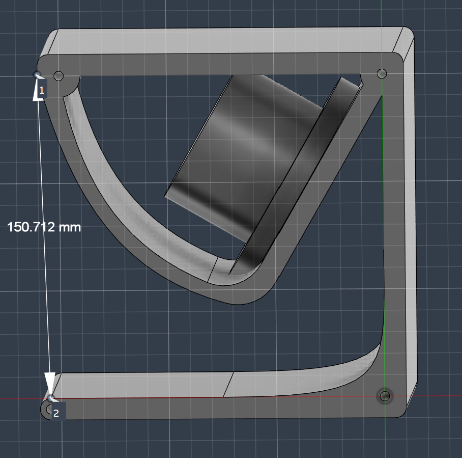
Next, we snake the horn path through the remaining cabinet footprint to maximize both path length ($L$) and exit mouth area ($S_m$). Accounting for $4.6 \text{ mm}$ wall thickness margins along the outer shell, the mouth width ($W_m$) opens to $150.71 \text{ mm}$, yielding a total mouth area ($S_m$) of $0.02411 \text{ m}^2$ ($150.71 \text{ mm} \times 160 \text{ mm} = 24,113.6 \text{ mm}^2$).
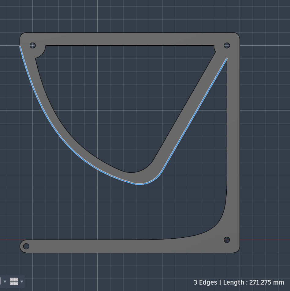
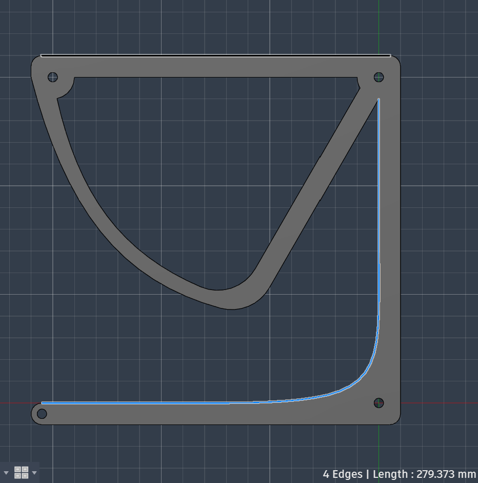
Measuring the internal curves in CAD reveals our boundary edge lengths:
- Lower (Inner) Boundary Length: $279.37 \text{ mm}$
- Upper (Outer) Boundary Length: $271.28 \text{ mm}$
- Mean Path Length ($L$): $\frac{271.28 + 279.37}{2} = 275.32 \text{ mm} \quad (0.2753 \text{ m})$
Assuming an exponential expansion model ($S_x = S_t \cdot e^{mx}$), we solve for our flare constant ($m$), which represents the tunnel's expansion rate:
$$m = \frac{1}{L} \ln\left(\frac{S_m}{S_t}\right) = \frac{1}{0.2753}\ln\left(\frac{0.02411}{0.0048}\right) \approx \mathbf{5.86}$$
Using the speed of sound in air ($c = 343 \text{ m/s}$), the flare constant establishes our internal flare cutoff frequency ($f_c$):
$$f_c = \frac{m \cdot c}{4\pi} = \frac{5.86 \cdot 343}{12.566} \approx \mathbf{160 \text{ Hz}}$$
While this internal flare path supports acoustic gain down to roughly $160 \text{ Hz}$, the real magic happens when the cabinet is placed on a table surface or near a rear wall. The boundary extends the effective mouth area ($S_m$), providing acoustic mass loading that should pull the impedance shoulder down. When the cabinet is assembled we are going to measure impendance response with the DATS V3.
Below this point, the horn unloads, and the $0.905 \text{ Q}_{tc}$ air spring in our rear chamber takes over cone control.
Handling the Highs: The Acoustic Consequences of Folding
While folding the acoustic path compresses a multi-centimeter horn into a portable $256\text{ mm}$ cube, forcing sound waves around $180^\circ$ turns introduces internal reflections. Higher frequencies struggle to navigate tight bends, resulting in mild comb-filtering ripples and standing-wave peaks in the $350\text{–}600\text{ Hz}$ range.
Rather than over-complicating the 3D geometry with heavy internal acoustic diffusers, we leverage our onboard digital signal processor. By applying a High-Pass Filter at 55 Hz to protect the driver from unloading excurison, alongside a targeted PEQ notch around 400 Hz, we flatten out internal fold resonances cleanly in software.
When torqued down, the 3D-printed cabinet shells compress our 1mm TPU gaskets, pulling the entire sandwich together into a singular, structurally unified, highly efficient splash-resistant outdoor speaker. The 8mm loosefiber matts inside will further help managing cabinet resonance.
Handling the Highs: The Acoustic Consequences of Folding
While folding the acoustic path compresses a multi-centimeter horn into a portable $256\text{ mm}$ cube, forcing sound waves around $180^\circ$ turns introduces internal reflections. Higher frequencies struggle to navigate tight bends, resulting in mild comb-filtering ripples and standing-wave peaks in the $350\text{–}600\text{ Hz}$ range.
Rather than over-complicating the 3D geometry with heavy internal acoustic diffusers, we leverage our onboard digital signal processor. By applying a High-Pass Filter at 55 Hz to protect the driver from unloading excurison, alongside a targeted PEQ notch around 400 Hz, we flatten out internal fold resonances cleanly in software.
When torqued down, the 3D-printed cabinet shells compress our 1mm TPU gaskets, pulling the entire sandwich together into a singular, structurally unified, highly efficient splash-resistant outdoor speaker. The 8mm loosefiber matts inside will further help managing cabinet resonance.
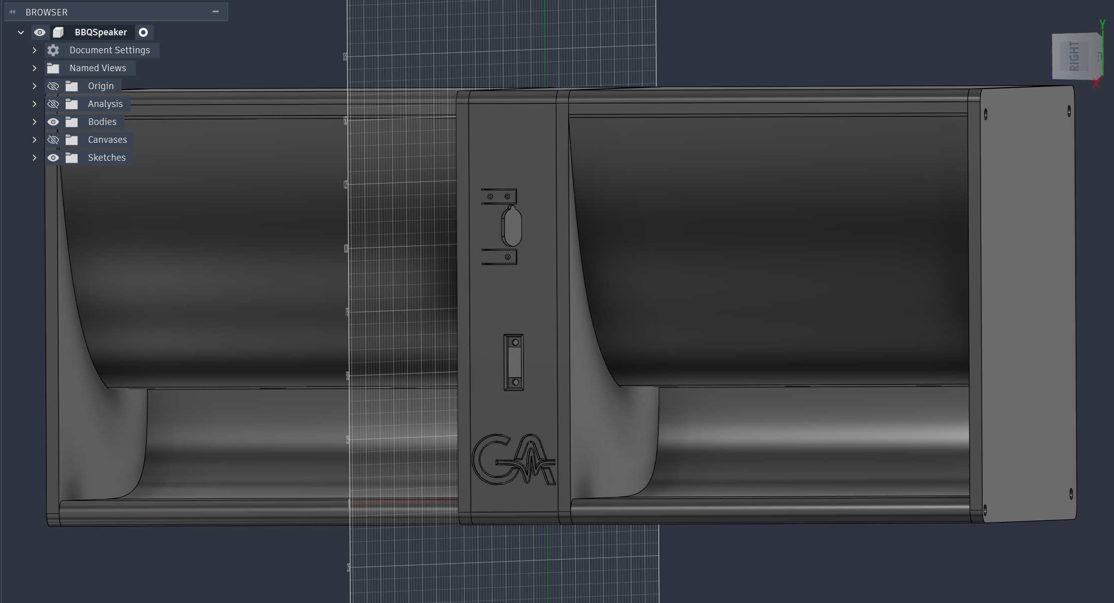
BBQ-Speaker Design
Future Work: Measurement & DSP Calibration
To fine-tune the final acoustic output, the assembled PETG prototype will be measured in an open-air environment using a calibrated measurement microphone. Based on our acoustic model, the onboard Bluetooth module’s Parametric EQ (PEQ) will be used to dial in a precise 3-filter correction profile:
- Subsonic Protection (HPF): A High-Pass Filter will be set to prevent sub-audible signals from driving the small 3-inch cone into over-excursion below the horn’s unloading threshold.
- Mid-Bass Enhancement: A modest parametric boost that rides the boundary mass loading shoulder to give kick drums and basslines a rich, punchy presence outdoors.
- Internal Fold Notch: 1 or a few narrow parametric cut to smooth out the primary acoustic reflection ripple created by the internal cabinet turns.
